
Continued from Part 4
I looked at the design of the transmitter again, thinking about where all the VHF energy could be coming from. The transmit signal is generated by the Si5351A synthesizer module, and then goes directly to the FET Power Amplifier (PA). Low pass filters for each band are then switched into the output to remove harmonics.
The synthesizer generates a square wave, which by its nature contains all the odd-integer harmonics of the fundamental frequency. This is the source of the VHF.
The fundamental and all the harmonics are amplified by the PA, and then filtered by the lowpass filters for each band installed in the kit. The PA also introduces harmonic distortion due non-linearities. (This contribution is what was reduced when I lowered the PA bias point to reduce the harmonics, as described in part 4).
So what about an approach that removes the VHF harmonics before they’re amplified?
It would be possible to add lowpass or bandpass filters before the PA to reduce the harmonics, but that would essentially be a duplication of the output filters which already exist, and add to the cost and complexity of the kit. It’s much simpler to just feed the synthesizer output to the PA and then filter everything after it’s amplified, and that’s the way this transmitter is designed.
The design of the kit is such that if you want to, you can operate it at VHF frequencies – the same frequencies I was trying to suppress. Installing a filter after the synthesizer to stop VHF would also make it impossible to operate at VHF frequencies.
The problem is that VHF energy is ‘leaking’ past the output filters and appearing at the output. Some of the causes for this are understood and documented in the study of harmonics on an earlier version of this kit. One change that was made with the current design of the kit is that the 10m LPF is always in the output path. This is specifically to block VHF, but this wasn’t adequate in my case.
I looked at all the spectrum plots from my various tests, and the harmonics that were present at the output were all approximately between 145 MHz and 200 MHz. As I wrote in the last post, I was able to affect the level of the VHF output spurs significantly by moving a grounded shield around inside the case, or putting the cover on. That led me to believe that the problem was radiation of VHF frequencies from the board and/or attached wires, which was coupling back into the output lead, or back into the board after the filters.
At this point, I didn’t really want to try to chase this much deeper. I’ve done enough of this type of troubleshooting to know that finding the absolute root cause and a fix for this is very challenging work. I just wanted my kit to meet part 97 and get on with putting it on the air.
I decided to try a fix specific to my use case. I only plan to use this transmitter on HF, with the highest frequency being the 10m band (28 MHz). This matches the set of filters that the Deluxe 6-band U3S set came with. I decided to install a LPF at the output of the synthesizer board, to filter out the harmonics close to the source before they got amplified by the PA.
I looked for the best place to insert a filter, and decided to do it on the synthesizer board. It’s removable to make it easy to work on, and would only cost less than $8 for a replacement if I were to completely trash it.
Looking at the synthesizer module board , I realized that I could cut a single trace on the bottom of the board and disconnect the module pin 17, which carries the signal (CLK0) to the main board. Pin 17 is located near the end of the board with the solder pads for the optional SMA connector for CLK0, which are used if you want to use the board as a standalone signal generator.
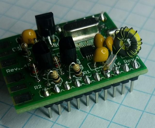
I started with a simple pi filter. I picked a cutoff frequency of 40 MHz, and used an impedance of 50 ohms, since that’s the output impedance of the Si5351A chip. The inductor value is .400 uH, which I made with 12 turns of AWG 30 wire on a T25-6 toroid that I had on hand. The two capacitors are each 82 pF. The T25 toroid is the perfect size to put between the rf output pad on the end of the synthesizer board and pin 14, and the ground pads on the end of the board make convenient places to solder the ground ends of the capacitors. After these photos were taken, I anchored the inductor to the board with a drop of hot melt glue.
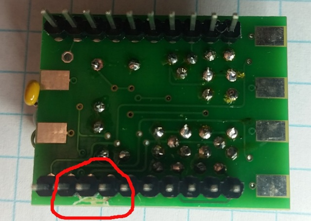
Here’s the trace I cut
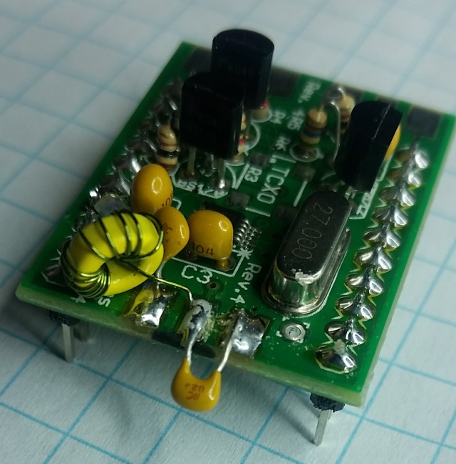
And here’s how the filter was installed
The results were great! it worked exactly as I’d hoped. It didn’t change the power output on 10m, which means I’d picked a high enough cutoff frequency for the filter. The VHF harmonics were gone, except for one spur that was more than 10 dB below the part 97 requirements. on 80m the second harmonic is close to the limit, but still passes.
Here are the final results:
| Band | Frequency | Power (dBm) | Harmonic spur (relative) | VHF spur (relative) | Test Image |
|---|---|---|---|---|---|
| 10m | 28,126,075 | 19.53 | -49.29 | -54.20 | Image |
| 15m | 21,096,075 | 21.23 | -49.29 | N/A | Image |
| 20m | 14,097,075 | 23.30 | -44.73 | N/A | Image |
| 30m | 10,140,175 | 20.63 | -48.18 | N/A | Image |
| 40m | 7,040,075 | 21.79 | -45.76 | N/A | Image |
| 80m | 3,594,075 | 22.98 | -43.26 | N/A | Image |
I’m happy with that, and it’s back on the air. If you want to see where that 200 mW signal has been heard, you can search for my call sign (AI4QR) on the WSPR reporting site.
Note: After everything else settled, I replaced the crystal on the synthesizer board with a TCXO, as covered in the synthesizer manual. I used the recommended part, a FOX924B-27.000. With the original crystal and GPS calibration turned on, I was getting reports from spotting stations that measured my frequency drift at between 0 and 4 Hz. This was acceptable but I wanted to see what difference the TCXO would make. After the change, most reports have a drift of zero, and at most 2 Hz.
My final thoughts are that this was a really nice kit to build, and QRP Labs is providing great value with the performance that you get for the price. It’s a nice product that has obviously had a lot of work put into the design over an evolution of the product. The community provides help and encouragement to people who have troubles getting things working.
Also, operating a WSPR beacon is a lot of fun.
If you care about part 97 compliance (and I think you should) then unless you have access to test equipment, it’s hard to know whether the completed kit meets those requirements. If you can, try to test your unit. If you can’t test, go light on the PA bias.
If you’re operating only on HF, you can add a filter like I did and that should make sure you don’t have any VHF emissions problems.
Fortunately, spectrum analyzers are becoming more common as they become less expensive, and it’s getting easier to find friends or maker spaces who have one. It’s also a lot of fun and a great learning exercise to go through the test process.
I had a lot of fun with this, including chasing the harmonics.
